Build your first Arduino circuit: proper instructions
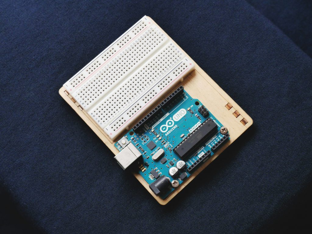
This first Arduino circuit makes an external LED follow a push button. It teaches the essential pattern of a digital input, an output, a current-limiting resistor, and a shared ground. Build it with the USB cable disconnected, then power the board from USB only. This is a low-voltage experiment: do not connect it to mains electricity, vehicle wiring, unknown batteries, or high-current loads.
Tools and parts
An Arduino Uno or compatible 5 V board, USB cable, computer, and Arduino IDE.
A solderless breadboard and male-to-male jumper wires.
One LED and a 220 ohm to 1 kilohm resistor; 330 ohms is a sensible starting value.
One four-leg momentary tactile push button.
A multimeter is useful for checking continuity, but not essential.
Know the layout
Five holes in one numbered breadboard row on either side of the centre gap are normally connected. The group on the other side is separate. Long power rails may be split in the middle, so inspect the markings rather than assuming continuity. An LED is polarised: its longer lead is normally the anode and its short lead or flat body edge is the cathode. The resistor limits current and must be in series with the LED; never put an LED straight from an Arduino pin to ground.
Numbered procedure
Disconnect USB. Place the LED across the central gap, so its legs cannot land in the same connected row.
Connect the LED cathode through the 330 ohm resistor to an Arduino GND pin. Connect the LED anode to digital pin 8.
Place the button across the centre gap. One pair of legs on a tactile button is commonly connected internally, and pressing connects that pair to the pair opposite. Straddling the gap prevents an accidental permanent connection through the breadboard.
Connect one button side to GND and the opposite side to digital pin 2. The program will use the microcontroller’s internal pull-up resistor, so no external button resistor is needed.
Inspect for a direct 5 V-to-ground short, ensure the LED has its resistor, and connect USB. In the IDE select the actual board and serial port, then upload:
const int ledPin = 8;
const int buttonPin = 2;
void setup() {
  pinMode(ledPin, OUTPUT);
  pinMode(buttonPin, INPUT_PULLUP);
}
void loop() {
  bool pressed = digitalRead(buttonPin) == LOW;
  digitalWrite(ledPin, pressed ? HIGH : LOW);
}
Test method
With no pressure on the button, the LED should be off.
Hold the button down. The LED should light, then go out when released.
If upload fails, confirm the selected board and port before changing the circuit.
If the LED never lights, test the board built-in LED example, then check LED orientation, the pin 8 lead, resistor path, and ground connection.
If the LED is always lit or the button seems always pressed, check that the button crosses the gap and that pin 2 is connected to the opposite switch side from ground.
With INPUT_PULLUP, an open switch reads HIGH and a pressed switch reads LOW. That inversion is correct. A bare input is floating and may read unpredictably, which is why the pull-up matters. Switches can also bounce briefly; that is normal for this direct indicator, but code which counts presses needs debouncing.
Common mistakes and safety
Putting both LED legs in one connected strip bypasses the LED.
Changing jumpers while powered can short rails. Unplug USB first.
Arduino pins are logic outputs, not supplies for motors, relays, LED strips, or heaters. Those need rated drivers, appropriate power, and protection such as a flyback diode where applicable.
Stop if wires or components get hot or you smell overheating; disconnect and inspect.
Record the board, pins, resistor value, and a photograph of the working layout. Change one thing at a time when extending it.
A USB-powered board is safer than mains, not indestructible. Keep metal objects off the breadboard and use a sound cable. For mains, chargers, batteries with high fault current, or mains-controlled devices, use proper isolated equipment and experienced supervision rather than adapting this exercise.
Check the circuit deliberately
Before USB is connected, trace the intended current path with your finger from pin 8, through the LED, resistor, and ground connection. Then trace the button path separately from pin 2 through the switch to ground. A multimeter in continuity mode can confirm a breadboard row or a doubtful switch, but use it only with the board unpowered. For a four-leg switch, test which two legs remain connected when unpressed and which pairs connect when pressed; packages can be rotated differently from the drawing you expected.
Use the IDE serial monitor to make invisible input states visible while learning. Temporarily add Serial.begin(9600) in setup and print the button reading in the loop, with a small delay so the monitor remains readable. Remove or revise that diagnostic after testing. If the LED seems weak, do not immediately reduce resistance: first verify its polarity and connections. The resistor value trades brightness for current, and component data sheets, not guesswork, define safe limits. Keep all grounds shared when you later add a suitable external low-voltage supply, but do not connect supplies until you understand their voltage and polarity.
Useful next test
After the basic response is reliable, move only the LED signal wire from pin 8 to another unused digital pin and update ledPin to match. Upload, test, and document the change. This simple exercise demonstrates that a program and physical wiring must agree exactly. If they disagree, the sketch can upload perfectly yet control nothing. When a circuit stops working after an alteration, return first to the last photographed, known-good arrangement rather than making several speculative changes at once.