Build an Arduino temperature monitor: proper instructions
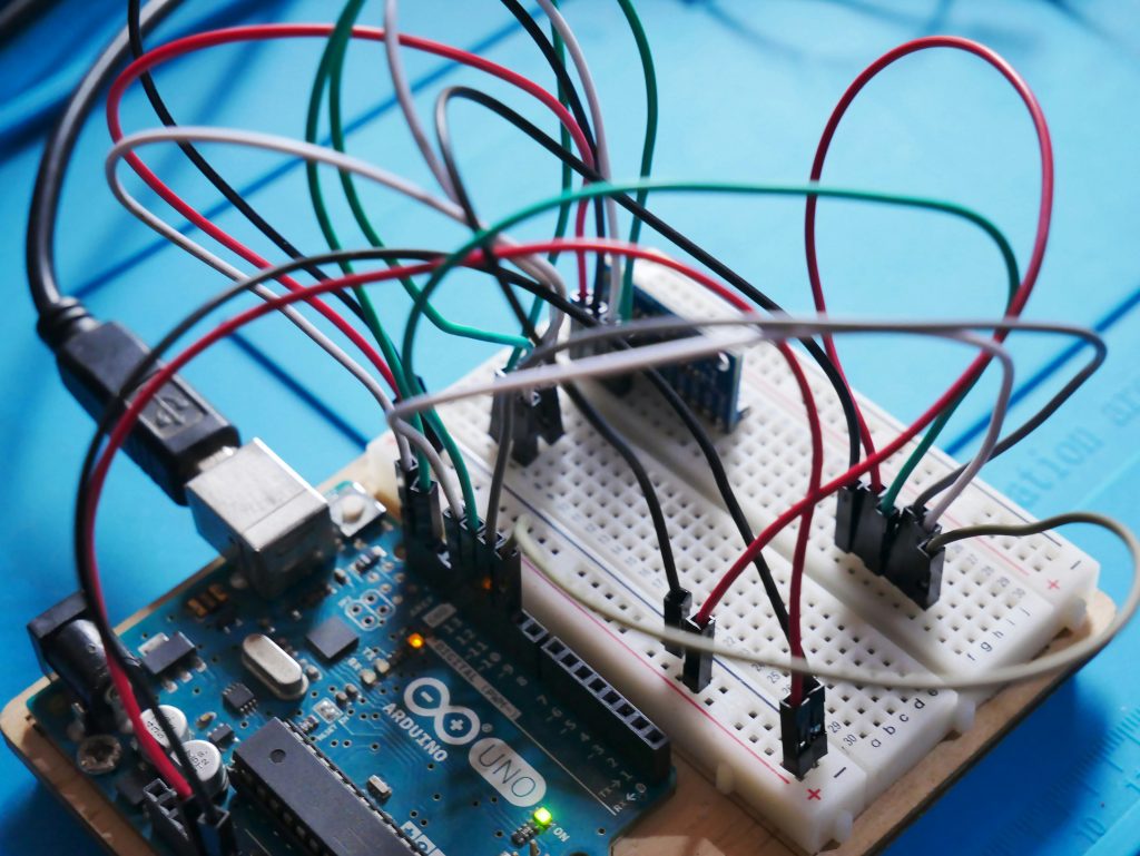
Make a small room-temperature display with an Arduino, a DS18B20 digital probe and a 16 by 2 I2C LCD. This is an indicator, not a thermostat: it must not control a boiler, heater, immersion element or mains appliance.
Parts
- Arduino Uno, Nano or compatible 5 V board and USB data cable.
- Three-wire DS18B20 probe and 4.7 kΩ resistor.
- 5 V 16 by 2 I2C LCD, breadboard and jumper wire.
Wiring
- Connect probe red to 5 V, black to GND and its data lead to D2; confirm the supplied colour code rather than assuming it.
- Fit the 4.7 kΩ resistor between data and 5 V. Without this pull-up the one-wire bus is unreliable.
- Connect LCD VCC to 5 V, GND to GND, SDA to A4 and SCL to A5 on an Uno/Nano. Use labelled SDA/SCL pins on other boards.
Software
Install Arduino IDE, select the board and port, then install OneWire, DallasTemperature and a compatible LiquidCrystal_I2C library. Start from each library example. In the final sketch, call sensors.requestTemperatures(), read getTempCByIndex(0), and display the result every two seconds. An I2C scanner sketch identifies the LCD address; common addresses are 0x27 and 0x3F, but neither should be guessed.
request temperature; read Celsius; if disconnected show “Probe not found”; otherwise print Celsius and Celsius * 9 / 5 + 32.Test and faults
- Confirm a normal indoor reading, then warm the probe gently in your hand and watch a gradual rise.
- Compare after settling beside a known thermometer. For a cool-water test, immerse only a sealed probe; keep USB electronics dry.
- If it shows -127 C, recheck probe colour order, power and the 4.7 kΩ resistor. A permanent 85 C often means conversion was not requested.
- If the LCD is lit but blank, scan I2C, inspect SDA/SCL, and adjust its contrast control.
Accuracy and limits
The probe measures its own location, not every part of a room. Avoid sun, radiators, draughts and sealing it inside a wall. A hobby sensor is unsuitable as the sole basis for food, medical, frost-protection or safety decisions. A threshold alarm added later can fail through reset, detached cable or sensor failure, so treat it as advisory.
Build carefully
Disconnect USB before moving wires. Work on a dry, uncluttered bench and use only the low-voltage supply provided by USB while developing the circuit. Check each connection against the label on the actual module, because clone boards can put connectors in a different order. A breadboard is useful for experiments but its contacts can work loose; do not leave an unattended project in a place where a lead can be pulled, crushed or exposed to water.
Record what you changed between tests. Change one setting, upload one revision, then repeat the same test. This is faster and safer than changing wiring, code and sensor position at once. Once the circuit works, add strain relief and an enclosure, but keep access for inspection and do not hide untested connections.
Before relying on any result
Repeat the test after changing the final location and after a power cycle. Label leads and keep notes of settings, dates and observed behaviour. Do not extend sensor leads indefinitely or substitute a power supply without checking voltage and current requirements. If behaviour changes without an explained reason, return to the last known-good wiring rather than bypassing a protective component or increasing supply voltage.
Review the result
Hobby electronics is most reliable when its assumptions are visible. Identify what creates an input, what the board decides, and what physical output follows. Consider loss of power, disconnected cable, loose breadboard contact, wrong software port, restart, accidental adjustment and environmental change. A successful five-minute demonstration proves only that it worked for five minutes under those conditions. Repeat tests after adjustments, and keep the project clearly labelled as a low-voltage experiment where others might otherwise assume it provides protection or control.
Practical checklist
Before each use, inspect the USB lead, board, insulation and sensor cable for damage. Confirm the board is powered from the intended low-voltage source and that its indicator behaviour agrees with the latest test. Keep the instructions, component part numbers and the current program with the project so that a future repair does not depend on memory. Do not leave a breadboard assembly where children, pets, moisture, metal objects or moving furniture can reach it. Disconnect power before repositioning conductors.
When diagnosing a problem, begin with the simplest observation: power indication, physical connector orientation, measured input state and program output. Use a known-good cable and a short test setup before adding extensions, enclosures or optional modules. Do not “fix” an uncertain fault by removing resistors, joining supply rails, increasing voltage or bypassing a switch. If a component becomes hot, smells unusual, repeatedly resets the board, or has damaged insulation, disconnect power and replace or investigate it before continuing.
Document both expected and unexpected results. Note the ambient conditions, sensor placement, delay settings and test duration. That evidence makes false triggers, questionable temperature readings and intermittent connections easier to distinguish from software mistakes. The finished device remains a hobby experiment: use independent, purpose-designed equipment wherever a missed event, incorrect measurement or failure to operate could cause loss, injury, regulatory breach or an emergency response.