Build a network cable tester: proper instructions
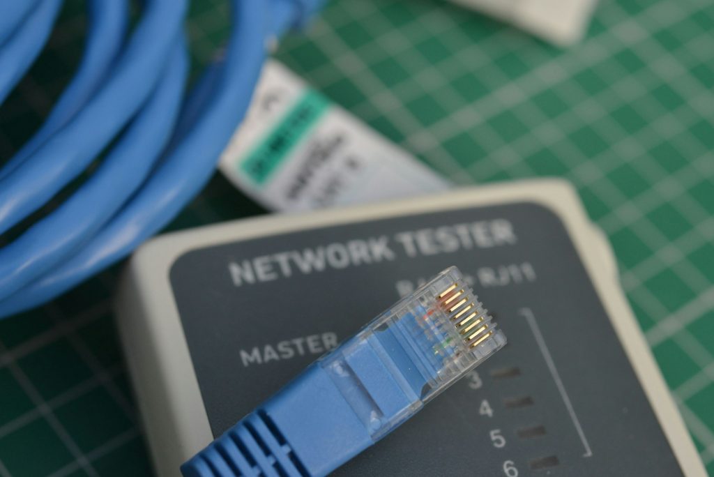
This is a basic continuity and wiring-order tester for disconnected Ethernet patch cables with 8P8C modular plugs, commonly called RJ45. It reports whether each of eight conductors reaches the expected pin at the far end, and can expose an open, a crossed conductor or a short. It cannot certify Cat5e/Cat6 performance, bandwidth, impedance, insertion loss, near-end crosstalk or PoE capability. Use a certified cable analyser for structured-cabling acceptance.
Prerequisites
• Two panel-mount 8P8C female sockets with accessible terminals.
• A breadboard or perfboard, hook-up wire, 9 V battery, battery clip and an insulating enclosure.
• Eight LEDs, eight 1 kΩ resistors, a momentary switch, a multimeter and wire tools.
• A known-good straight-through patch cable for calibrating the tester itself.
Numbered actions
1. Disconnect both ends of every cable from switches, routers, wall outlets, PoE injectors and telephones. Ethernet can carry power, including PoE. Never attach this tester to live equipment and never use it on mains wiring.
2. Map socket pins with a spare plug and the meter before wiring. With contacts facing you and latch away, pin 1 is leftmost. Map plug contacts to socket terminals, because rear labels may be mirrored, then tape labels 1 to 8 on each socket.
3. Connect battery positive to one side of a momentary switch. Put an insulated clip lead on its output; it will touch one socket A terminal at a time. Leave every unselected A terminal separate.
4. Connect battery negative to a common rail. Connect socket B pin 1 to LED 1 anode, then LED 1 cathode through one 1 kΩ resistor to the negative rail. Repeat separately for pins and LEDs 2 through 8.
5. Label the LEDs 1 to 8. LED colours are optional; numeric labels make a wiring-order diagnosis clear.
6. With the battery removed, test continuity in the tester. Each A pin must reach only its selector connection; each B pin must reach only its matching LED branch. Confirm no direct continuity exists from battery positive to negative.
7. Install the circuit in a non-conductive enclosure with strain relief. Do not leave a battery-connected breadboard loose where metal objects can short it.
Checking and testing
1. Connect the known-good disconnected cable between A and B and fit the battery.
2. Briefly select A pin 1. Only LED 1 should light. Repeat through pin 8, releasing the switch between checks to save battery power.
3. The expected order is 1, 2, 3, 4, 5, 6, 7, 8. No LED suggests an open wire, poor contact, flat battery or tester fault; another number suggests a cross or mirrored map.
4. If several LEDs light, remove the battery immediately and inspect for a short or shared branch. Verify the tester with the known-good cable before deciding a cable is bad.
Common mistakes
• Calling a continuity tester a cable certifier.
• Testing a cable still attached to network equipment or PoE.
• Omitting current-limiting resistors; each LED needs its own series resistor.
• Trusting socket orientation rather than mapping pins with a meter.
• Testing only pins 1, 2, 3 and 6, although gigabit Ethernet uses all eight conductors.
Rollback and safety
Remove the battery before storage, adjustment and diagnosis. If the reference cable gives a surprising result, troubleshoot the tester with the meter before condemning any installed cable. To dismantle it, remove the battery first and unplug or desolder one branch at a time. Label it as a disconnected-cable continuity tester so it is never mistaken for a live-network analyser or certification instrument.
Reading the results carefully
The test current travels through one conductor and one LED branch. A correct result establishes continuity and endpoint order for that conductor only. It does not prove that the twisted-pair geometry is preserved inside the cable, that contacts will remain reliable under movement, or that the cable meets high-frequency Ethernet specifications. A cable can pass this tester and still fail at gigabit speed because of split pairs, poor impedance or crosstalk. That is why commercial certifiers inject controlled signals and measure them at frequency.
Document any cable fault before cutting a plug off. Record the local pin selected, the remote LED observed and whether the same result repeats after reseating the cable. Dirty plug contacts and a loose connector can mimic a permanent open. A different LED consistently lighting identifies an order mismatch, while no response can also be caused by a depleted 9 V battery or reversed LED. Test the tester against its reference cable again after any repair. If you repair a cable, use the recognised T568A or T568B scheme consistently at both ends for a straight-through patch cable; do not infer colour order from this tester alone.
Battery and enclosure care
Use a fresh battery only long enough for tests and remove it after use. A battery left connected can leak or be drained through an accidental short. The enclosure should protect connections yet let you replace the battery without pulling wires. Do not make the tester into an inline network device, and do not add connectors that invite use on a powered wall port. A prominent label saying disconnected cables only is an effective safety control.