Make an LED blink without using Arduino: proper instructions
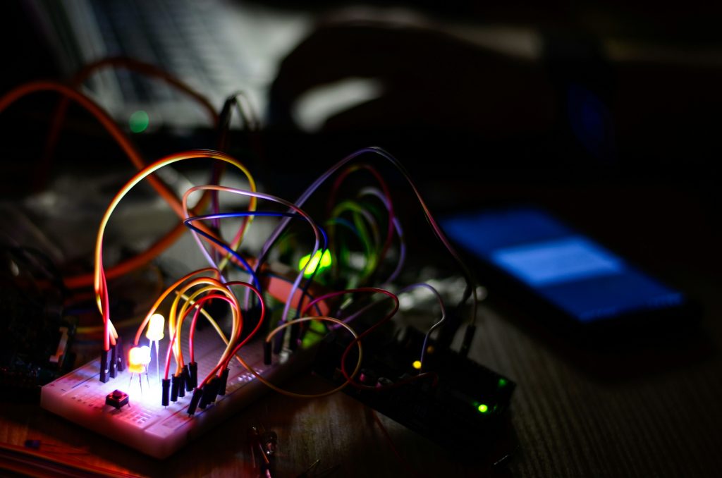
A 555 timer can blink an LED without software. In astable mode it repeatedly charges and discharges a capacitor, switching its output each cycle. This guide uses a standard NE555 on a breadboard at regulated 5 V. Timing varies with resistor and capacitor tolerance, so it is a teaching oscillator rather than a precision clock. Use only low-voltage regulated DC and never connect a breadboard circuit directly to mains.
Tools and parts
One NE555 timer in an 8-pin dual in-line package and a breadboard.
A verified 5 V breadboard supply, jumper wires, and ideally a multimeter.
One 10 kilohm resistor, one 100 kilohm resistor, and one 330 ohm to 1 kilohm LED resistor.
One 10 microfarad electrolytic capacitor rated above 5 V and one 10 nanofarad ceramic capacitor.
One LED.
Pin orientation
Put the notch or dot at the top. Pin 1 is lower left and numbering runs anticlockwise: pins 1 to 4 down the left, then 5 to 8 up the right. Pin 1 is ground, 8 is supply, 4 is reset, 3 is output, 2 and 6 are the timing sense pins, 7 discharges the timing capacitor, and 5 is the control-voltage pin.
Numbered procedure
Power off. Fit the 555 across the breadboard centre gap.
Connect pin 1 to ground, pin 8 to positive 5 V, and pin 4 directly to positive 5 V. Reset must be high for normal operation.
Join pins 2 and 6. Connect the positive lead of the 10 microfarad capacitor to this joined node and its stripe-marked negative lead to ground.
Connect 10 kilohms from positive 5 V to pin 7. Connect 100 kilohms from pin 7 to the joined pins 2 and 6.
Connect the 10 nanofarad ceramic capacitor from pin 5 to ground. Ceramic capacitors normally have no polarity.
Connect pin 3 through the LED resistor to the LED anode. Connect the LED cathode to ground. The resistor may be on either side of the LED provided it is in the same series path.
With power still off, inspect the IC orientation, capacitor polarity, rail continuity, and absence of a rail short. Measure the supply and confirm approximately 5 V before connecting it.
The usual ideal estimate is high time 0.693 times (R1 + R2) times C and low time 0.693 times R2 times C. With the values above, the blink is about 1.45 seconds per cycle in an ideal calculation. Real values differ, particularly for an electrolytic capacitor.
Testing and fault finding
Apply power: the LED should alternate on and off.
Measure pin 3 relative to pin 1 with a DC meter. It alternates between low and near the supply, though a basic meter may show an average.
Change only the 100 kilohm resistor to alter the rate, disconnecting power before every change.
If it does not blink, check pin numbering, the pin 2-to-6 link, reset at pin 4, broken power rails, and the LED orientation.
Common mistakes and safety
Rotating the chip misplaces supply connections. Always orient from its notch or dot.
Leaving reset floating causes erratic operation; tie pin 4 high.
Omitting the LED resistor can overcurrent the LED or output.
Reversing the electrolytic capacitor can damage it. Disconnect power if it warms, swells, leaks, or smells unusual.
Some breadboard rails split halfway; bridge only after checking the markings.
Do not expect exact timing from ordinary parts. Use suitable calibrated or crystal-based timing where accuracy matters.
Disconnect before moving wires and do not bridge powered rails with probe tips or tools. If any component or supply heats unexpectedly, unplug immediately and inspect rather than repeatedly reapplying power. The 555 output is not a general power source: a motor, relay, or larger load needs a properly designed driver and supply.
Why the values matter
During charging, current reaches the timing capacitor through both timing resistors; during discharge, pin 7 provides a path through the lower resistor. That is why the two halves of the cycle are not identical with this simple arrangement. If you fit a much larger capacitor, it may take several seconds before the first visible transition, so wait before assuming it failed. If you fit a very small capacitor or resistance, the LED can appear continuously lit because your eye cannot resolve the rapid switching.
Keep wiring short and orderly. Long loose jumpers can pick up noise and make a simple circuit harder to inspect. A ceramic decoupling capacitor placed close between the IC supply pins is a useful addition for more robust breadboard work; follow the timer data sheet and keep its leads short. Do not substitute an unknown IC just because it has eight pins. Check its marking and pinout. When using a bench supply, set a conservative current limit before powering the circuit; it can reduce damage from a wiring error, but it does not make a fault safe to ignore.
Safe modifications
To make the rate adjustable, replace part of the timing resistance with a potentiometer only after checking its resistance range and wiring. Set it near the middle before power-up, then change it slowly while observing the LED. Do not use a potentiometer as a substitute for the LED current-limiting resistor. If you later connect a transistor stage, identify the transistor pinout from its data sheet, add the necessary base or gate components, and verify the load supply separately. A common ground is often required for a control signal, but connecting grounds carelessly between unknown power systems can create faults.
Write down every value actually fitted, because resistor colour bands and capacitor markings are easy to misread. Measure doubtful components before use. A systematic record of supply voltage, output behaviour, and component values turns fault finding into comparison rather than guessing.